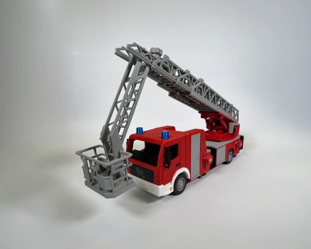
In this assembly guide, we will show you step by step how to assemble your Drehleiter-Trainer as a self-assembly kit Assemble. The individual assembly steps are accompanied by videos and written instructions, so you can easily identify the components and assemble the Aerial Ladder Trainer yourself.
The Aerial Ladder Trainer consists primarily of plastic components and contains some delicate and moving parts. Careful assembly is therefore particularly important to avoid damage and injury.
Please read the following safety and assembly instructions completely before beginning assembly.
General safety instructions
- Assembly may only be carried out by persons who possess the necessary knowledge of how to safely handle the tools used. Minors may only carry out assembly under appropriate supervision.
- Perform all assembly steps on a stable, level and sufficiently large work surface.
- Keep children and bystanders away from the work area during assembly. The kit contains small parts that could be swallowed and is not a toy.
- Use appropriate personal protective equipment if necessary, especially safety glasses when working with hammers or tools.
- Before starting assembly, check all components for visible damage and completeness. Damaged or defective components must not be installed without prior consultation with the BOS-Akademie.
Intended use of tools
Various tools are needed for assembly, including a hammer, cordless screwdriver and water pump pliers.
- Tools may only be used in accordance with their intended purpose and the respective manufacturer's instructions.
- Use only suitable, technically sound tools.
- Observe all safety and operating instructions provided by the tool manufacturers.
- Work with controlled force and avoid jerky or uncontrolled movements.
- When using a cordless screwdriver, it is important to pay attention to a suitable speed and appropriate torque.
- When inserting round materials using a cordless screwdriver, as shown in the assembly videos, particular attention must be paid to secure clamping, a firm hold of the components, and the prevention of injuries from rotating parts. This procedure may only be carried out if it is safe and can be performed correctly with the tool being used.
- Use a hammer only in the designated areas. Do not subject delicate or exposed plastic parts to uncontrolled pressure.
- Secure and support the components adequately during assembly, especially when tapping in round materials.
BOS-Akademie accepts no responsibility for damages resulting solely from improper or unintended use of tools and not attributable to circumstances for which BOS-Akademie is responsible. Statutory liability claims remain unaffected.
Protection of components during assembly
The components of the Aerial Ladder Trainer are predominantly manufactured using 3D printing. Due to the material properties, special care is required during assembly.
- Do not apply excessive force. When working with resistors, first check the alignment and fit of the components.
- Screws must not be overtightened, as this can damage plastic components.
- Round materials must be inserted straight and in a controlled manner. Tilting can lead to damage to the holes or adjacent components.
- Components may not be modified by drilling, grinding, cutting or other mechanical processing unless expressly permitted or approved by BOS-Akademie.
- Use adhesive only in the areas specified in the instructions. Ensure that no movable joints are unintentionally glued together.
- Observe the safety instructions and curing times provided by the adhesive manufacturer.
Damage demonstrably caused by improper assembly, excessive force, incorrect use of tools or unforeseen modifications does not, in itself, constitute a product defect.
Assembly instructions and sequence
- The assembly steps must be carried out in the specified order, unless explicitly stated otherwise.
- Please follow both the written instructions and the accompanying assembly videos.
- Use only the components and fasteners intended for each step.
- After each assembly step, check that the components are correctly and completely connected.
- Do not continue assembly if components cannot be connected as intended or if there are any uncertainties during assembly. In this case, contact BOS-Akademie first.
Moving components and functional testing
The Aerial Ladder Trainer has numerous moving components, including bogie, ladder set, hydraulic cylinders, supports and basket.
- After assembly, check that all moving components can be moved and fixed properly.
- Movable connections must not be tightened excessively.
- Avoid jerky movements and forcibly overcoming mechanical stops.
- When moving the ladder set, be careful to avoid potential pinch points.
- Keep fingers and other body parts away from joints, sliding elements, and moving connections.
- Do not use the Aerial Ladder Trainer if components are damaged, loose, or not properly attached.
Use and load limits
The Aerial Ladder Trainer is a scale training model for illustrating and simulating operational situations in fire service training.
- The model is intended solely for the designated training and demonstration purpose.
- It is not suitable for carrying or lifting real people or heavy objects.
- The ladder set, basket and accessories must not be subjected to loads exceeding their designed load limits.
- The model must not be used as a climbing aid, toy or for any other unintended uses.
- Place the Aerial Ladder Trainer on a flat, stable surface during use.
- When extending and rotating the ladder set, ensure sufficient clearance and a secure position for the model.
Protection from heat and sunlight
The Aerial Ladder Trainer consists primarily of temperature-sensitive plastic components.
- Set the model not exposed to direct sunlight or high temperatures for extended periods.
- In particular, do not leave the Aerial Ladder Trainer in a hot vehicle or directly next to heat sources.
- Store the model in a dry place, protected from dust if possible and from direct sunlight.
- Avoid strong mechanical stresses during storage and transport.
High temperatures can lead to permanent deformation and impairment of function.
Liability and warranty
The Aerial Ladder Trainer is assembled independently by the buyer using the provided assembly instructions.
BOS-Akademie is liable within the scope of the statutory provisions. Damages that arise solely from improper assembly, use contrary to the intended purpose, use of unsuitable tools, unauthorized modifications or disregard of the safety and assembly instructions, and for which BOS-Akademie is not responsible, do not give rise to any liability on the part of BOS-Akademie.
Liability for damages resulting from injury to life, body, or health caused by a culpable breach of duty by BOS-Akademie or its legal representatives or agents, as well as for damages resulting from intentional or grossly negligent breaches of duty, remains unaffected. The same applies to other mandatory statutory liability provisions.
The statutory warranty rights remain fully in effect. In particular, claims arising from defects in materials, manufacturing, or assembly instructions that were already present at the time of delivery are not excluded by these instructions.
Questions or problems during assembly
Should any difficulties arise during assembly, components not fit as intended, or damage be detected, interrupt the assembly at the affected point.
If in doubt, contact BOS-Akademie before carrying out further assembly steps or making any changes to the components yourself.
We are happy to assist you with any questions you may have regarding the assembly of your Aerial Ladder Trainer.
1. Vehicle frame
1.1. Prepare the vehicle frame
Prepare the largest part of the vehicle frame as a base for the following assembly steps.
Pay attention to the orientation: The wheel recesses should point downwards. The wider end forms the front of the vehicle, where the driver's cab will later be mounted.
1.2. Installing rear stairs
Take the two black stair elements for the left and right sides of the vehicle and slide them from above into the designated recesses at the rear end of the vehicle frame.
Pay attention to the correct orientation: The higher side of the stair elements should point inwards towards the wheel, the lower side towards the rear of the vehicle.
1.3. Install the rear panel
Slide the rear panel down onto the designated guide rails at the rear end of the vehicle frame until it is fully seated.
Pay attention to the correct alignment: The holes in the rear panel must be at the bottom and align with the holes in the vehicle frame.
1.4. Install the rear bumper
Apply some adhesive to the two short, right-angled mounting pins of the rear bumper.
Then slide them through the holes in the rear panel into the corresponding holes in the vehicle frame until the bumper is fully seated.
1.5. Insert hexagon nuts
Insert the 12 M6 hex nuts into the designated recesses on the top of the vehicle frame.
1.6. Inserting maternal supplements
Insert the 12 black M6 nut washers into the designated recesses on the top of the vehicle frame, so that they each rest directly on the previously inserted hexagon nuts.
1.7. Install the cover plate
Slide the grey cover plate from front to back onto the designated guide rails on the top of the vehicle frame.
1.8. Insert ball bearing and spacer ring
Turn the vehicle frame over so that the underside is facing upwards.
First, insert a deep groove ball bearing into the central, round recess of the vehicle frame. Then, place the black ball bearing spacer ring on top and insert a second deep groove ball bearing.
1.9. Attach felt strips to the pivot bolt
Peel off the protective film from the self-adhesive felt strip and stick it all the way around the outer, circumferential ring of the swivel bolt.
1.10. Insert pivot bolt
First, insert the black counterpart of the pivot bolt into the designated recess on the underside of the vehicle frame. Ensure that the protruding, round part extends into the opening of the vehicle frame.
Then turn the vehicle frame over again so that the top side is facing upwards.
Now insert the swivel bolt into the opening from above. The smooth surface with the largest diameter must be facing upwards.
Gently tap the pivot bolt in with a hammer until the top surface rests completely on the vehicle frame.
1.11. Remove the counterpart of the pivot bolt
Turn the vehicle frame over again so that the underside is facing upwards. Then remove the black counterpart of the pivot bolt from the recess.
1.12. Install the engine room seat roof
Legen Sie das Drehgestell-Grundteil, das graue Maschinistensitzdach sowie das Rundmaterial (Ø 2 mm, Länge: 25 mm) bereit.
For assembly, use the assembly aid A, position 1. Slide it between the operator's seat and the center section of the bogie so that the back of the assembly aid faces the seat.
Next, attach the operator's seat roof to the designated position and insert the round stock through the corresponding holes. Carefully tap it fully into place with a hammer to connect the roof to the seat.
Finally, check that the operator's seat roof can be opened and closed without any problems.
1.13. Assemble the bogie
Position the vehicle frame with the top side facing up. Place the bogie on the vehicle frame so that the holes of both components align.
Then perform a Hex bolt M8 × 70 from above through the bogie into the bore of the vehicle frame.
Hold the screw firmly and carefully turn the vehicle frame over so that the underside is facing upwards.
Insert the black nut holder into the designated recess. Ensure that the receptacle for the M8 hex nut Pointing upwards. Insert the nut and press it firmly into the holder.
Turn the vehicle frame over again and tighten the screw from above using a cordless screwdriver. Secure the nut on the underside to prevent it from turning.
Important: Do not overtighten the screw. Finally, check that the bogie rotates smoothly and evenly.
1.14. Install supports
Important: This assembly step must be completed in total four times This can be carried out because all four supports are mounted identically.
Place the red support, the grey support, the black foot, and the red Locking handle Ready. Additionally, an M6 × 25 hex bolt, an M6 washer and an M6 hex nut are required.
Press the hexagonal screw into the designated recess of the red locking handle.
Insert the M6 nut into the corresponding recess of the grey support.
Slide the grey support into the designated opening of the red support. Ensure correct orientation: The side with the inserted nut should face the closed side of the red support.
Next, place the washer onto the screw of the locking handle and screw it through the side opening into the opening of the inserted nut.
Now apply some adhesive to the designated recess in the black base and insert the support. Gently tap the components together with a hammer until they are fully bonded.
Then turn the support over and gently tap it again from the foot side to ensure a secure fit.
1.15. Insert the rims into the tires
Prepare the four tires and their corresponding rims.
Pay attention to the correct placement: The two rear tires and rims are wider than the front ones. The textured side of the rims is the visible side and will later face outwards from the wheel well.
Press the appropriate rims into the respective tires until they are fully and evenly seated.
1.16. Connect the wheels to the axles
Prepare the two axles (round material Ø 4 mm, length 117 mm) and the four prepared wheels.
Turn the wheels so that the less detailed side of the rims is facing up. Then, place a small drop of glue into the center hole of each rim.
Insert one axle into the hole of one wheel and tap it into place with a hammer. Then attach the second wheel to the opposite side of the axle.
Repeat the process for the second pair of wheels. Ensure that two front wheels and two rear wheels are connected together.
Important: Finally, compare the overall length of both wheel-axle units. They must be the same length. If necessary, carefully tap the axles further into the rims.
1.17. Installing roller shutters
Prepare the vehicle frame and the two roller shutters.
Apply some adhesive to the designated contact surfaces on the vehicle frame. Then insert the roller shutters into the corresponding recesses and gently tap them into place with a hammer.
Repeat the process on the opposite side of the vehicle so that a roller shutter is installed on both sides.
1.18. Attach felt strips to the counterpart of the swivel bolt.
Prepare the black counterpart of the swivel bolt and two self-adhesive felt strips.
Remove the protective film from the felt strips and stick them onto the two protruding tabs on the sides of the corresponding piece. Ensure that the felt strips are positioned correctly on the designated surfaces.
1.19. Install rear supports and wheel axle
Prepare the vehicle frame, two of the previously mounted supports, and the rear wheel axle with the wider tires.
Turn the vehicle frame over so that the underside is facing upwards.
Insert the two supports into the designated openings in the vehicle frame. Ensure that one support protrudes to the left and one to the right from the vehicle frame.
Next, insert the rear wheel axle into the designated recess above the round ball bearing mount.
Now place the black counterpart of the swivel bolt on top, so that the two supports and the wheel axle are underneath it.
Then proceed six M6 × 50 screws through the designated holes of the counterpart and tighten them with a cordless screwdriver.
Important: Tighten the screws sufficiently to ensure all components are securely fixed. However, avoid overtightening to prevent damage to the components.
2. Driver's cab
2.1. Insert hexagonal nuts into the driver's cab
Prepare the red driver's cab and four M6 hex nuts.
Press the four nuts into the designated recesses inside the driver's cab. Ensure that the nuts are fully seated in the recesses.
2.2. Insert interior
Take the black interior with seats and dashboard and insert it into the driver's cabin from the rear through the open back.
Gently push the interior inwards until it is fully seated in the driver's cabin.
2.3. Install mirrors and door handles
Prepare both wing mirrors and the door handles.
Insert the components into the designated holes on the outside of the driver's cab and gently tap them into place with a hammer.
Important: When checking the exterior mirrors, tap on the corners if possible to avoid damage.
2.4. Install blue lights
Prepare the two blue lights.
Insert these into the designated brackets on the roof of the driver's cab and gently tap them into place with a hammer until they are fully seated.
2.5. Install wheel arch and front panel
Prepare the two wheel arch parts (left and right), the front panel and the driver's cab.
First, insert the front panel into the designated guide rail of the left wheel arch section. Then, attach the right wheel arch section to the front panel from the opposite side, ensuring both parts are flush.
Finally, place the driver's cab onto the assembled components from above.
2.6. Attach felt strips to the driver's cab floor panel
Prepare the driver's cab floor panel with the two front steps and two self-adhesive felt strips.
Remove the protective film from the felt strips and stick them onto the two protruding ridges on the sides of the base plate. Ensure that the felt strips are in contact with the designated areas.
2.7. Assemble the front wheel axle and base plate
Turn the driver's cab upside down so that the underside is facing upwards.
Insert the front wheel axle into the designated recesses in the wheel arch parts.
Next, place the driver's cab floor panel on top so that the wheel axle is underneath it.
Now proceed vier M6 × 65 Schrauben Insert the screws into the designated front holes in the base plate (two on the left and two on the right) and tighten them with a cordless screwdriver.
Important: Tighten the screws sufficiently to ensure all components are securely fixed. However, avoid overtightening to prevent damage to the components.
2.8. Connecting the driver's cab to the vehicle frame
Prepare the vehicle frame and turn it over so that the underside is facing upwards.
Insert the two remaining supports into the designated recesses in the vehicle frame. Ensure that one support protrudes to the left and one to the right.
Next, assemble the driver's cab with the vehicle frame. The pre-installed driver's cab floor panel bridges the two components and connects them.
Now proceed six more M6 × 50 screws Insert the screws into the remaining free holes on the part of the base plate that rests on the vehicle frame and tighten them with a cordless screwdriver.
Important: Tighten the screws sufficiently to ensure all components are securely fixed. However, avoid overtightening to prevent damage to the components.
2.9. Install roller shutters on the access unit
Prepare the ascent unit and the two grey roller shutters.
Apply a small amount of adhesive to the designated contact surfaces of the access unit. Then insert the roller shutters into the corresponding recesses and gently tap them into place with a hammer until they are fully seated.
Repeat the process on the opposite side.
2.10. Insert hexagonal nuts into the ascent unit
Prepare the hexagonal nuts and the black nut holders.
First, insert the nuts into the designated recesses on the flat side of the ascent unit.
Next, press the black nut holders into the same recesses so that the nuts are completely covered and the recesses are flush.
2.11. Assemble the ascent unit
Turn the vehicle over so that the top side is facing upwards.
Insert the access unit from above into the designated recess directly behind the driver's cab. Ensure correct orientation: the smooth side of the access unit should face the driver's cab.
Then turn the vehicle over again so that the underside is facing upwards.
Perform the the last two M6 screws Insert them into the remaining free holes and tighten them with a cordless screwdriver.
Important: Tighten the screws sufficiently without overtightening them to avoid damaging the components.
2.12. Install the radiator grille
Prepare the radiator grille with the BOS-Akademie lettering.
Insert it into the designated recess on the front of the driver's cab and press it firmly until it is fully and flush.
3. Ladder Set
3.1. Insert hexagonal nuts into the ladder guide.
Prepare the red ladder guide and six M4 hex nuts.
Press the nuts into the designated recesses on what will later be the underside of the ladder set guide.
Then carefully tap the nuts into place with a hammer until they are fully seated in the recesses.
3.2. Install the ladder set guide
Turn the ladder set guide over so that the top side is facing upwards.
Place the widest ladder section on the guide and align it so that the holes of both components are on top of each other.
Then proceed six M4 × 12 screws Insert them into the designated holes and tighten them with a cordless screwdriver.
Important: Tighten the screws sufficiently without overtightening them to avoid damaging the components.
3.3. Install the blue light
Prepare the blue light.
Apply a small amount of adhesive to the designated mounting surface of the ladder guide. Then, attach the blue light and press it firmly into place.
3.4. Mounting hydraulic cylinder eyes
Prepare the two hydraulic cylinder eyes and the two piston rods (round material Ø 4 mm, length 84 mm).
First, apply some adhesive to the blind hole (the hole that does not go all the way through) of a hydraulic cylinder eye.
Next, insert the piston rod into the bore and gently tap it into place with a hammer until it is fully seated.
Important: Repeat this process with the second hydraulic cylinder eye and the second piston rod.
3.5. Mount the hydraulic cylinder eyes on the ladder guide.
Prepare the round material (Ø 4 mm, length 75 mm) and the two previously mounted hydraulic cylinder eyes.
Carefully insert the round stock into the front holes on the underside of the ladder set guide. These are located on the side where the ladder set section protrudes beyond the guide.
Slide the first hydraulic cylinder eye between the two protruding brackets and align the holes. Carefully tap the round stock through with a hammer until it reaches the next bracket.
Next, insert the second hydraulic cylinder eye and tap the round material completely through all the holes.
Make sure that the round material is flush on both sides at the end and does not protrude laterally.
3.6. Mount the hydraulic cylinder on the bogie
Prepare the two hydraulic cylinders and the round material (Ø 4 mm, length 104 mm).
First, clamp the round material into a cordless screwdriver.
Insert the first hydraulic cylinder into the designated guide on the exposed side of the bogie. Align it so that the bore of the hydraulic cylinder aligns with the bore in the bogie.
Using a cordless screwdriver, rotate the round material a short distance through the holes.
Next, insert the second hydraulic cylinder on the opposite side near the operator's seat and align the holes with each other.
Now, rotate the round stock through all the holes as far as possible. Gently tap the remaining piece in with a hammer until the round stock is fully seated.
Finally, check that both hydraulic cylinders can move freely and evenly.
3.7. Prepare the ladder set locking handle
Prepare the ladder set locking handle, an M10 × 100 hex bolt and an M10 washer.
Insert the screw from above into the designated opening of the locking handle and gently tap it in with a hammer until the screw head is flush with the handle.
Then slide the washer onto the screw.
3.8. Mount the ladder guide on the bogie
Prepare the prepared ladder guide and an M10 hex nut.
First, press the M10 nut into the designated recess on the side of the ladder guide until it is flush.
Next, insert the two piston rods of the hydraulic cylinder eyes into the previously mounted hydraulic cylinders on the bogie.
Now insert the prepared ladder set locking handle from the opposite side and screw it into the M10 nut to secure the ladder set guide to the aerial ladder. Ensure that the screw engages correctly in the nut.
Important: Loosen the locking handle slightly and check if the ladder guide can be pivoted up and down. Tightening the handle should fix the ladder guide in the desired position.
3.9. Install the first ladder set lock.
Prepare the three grey ladder set locks, the assembly aids A and B, and the widest unassembled ladder set section.
First, use the largest of the three locking mechanisms and the round material (Ø 2 mm, length 59 mm).
Position the ladder set in the mounting aids so that Mounting aid B at the lower end and Mounting aid A at the upper end the ladder is located.
Next, insert the locking mechanism into the designated position on the underside of the ladder set. Ensure that the straight side of the locking mechanism faces the bottom of the ladder and that the holes in the locking mechanism and the ladder set align.
Insert the round stock through the side holes of the ladder set and the hole of the locking mechanism. Carefully tap it in completely with a hammer.
Important: The round stock must be completely countersunk and must not protrude laterally. If necessary, use another piece of round stock as an aid to fully tap the rod in.
3.10. Install the second ladder set lock.
Prepare the widest of the unassembled ladder components, the taller of the two remaining grey locking devices, and the round material (Ø 2 mm, length 46 mm).
Position the ladder set section in the mounting aids A and B as in the previous step.
Next, insert the locking mechanism into the designated position on the underside of the ladder set. Ensure that the straight side of the locking mechanism faces the bottom of the ladder and that the holes align.
Insert the round stock through the side holes of the ladder set and the hole of the locking mechanism. Carefully tap it in completely with a hammer.
Important: The round stock must be completely countersunk and must not protrude laterally. If necessary, use another piece of round stock as an aid to fully tap the rod in.
3.11. Install the third ladder set lock.
Prepare the last unassembled ladder set part, the remaining grey locking device, and the round material (Ø 2 mm, length 33 mm).
Position the ladder set section in the assembly aids A and B as in the previous steps.
Next, insert the locking mechanism into the designated position on the underside of the ladder set. Ensure that the straight side of the locking mechanism faces the bottom of the ladder and that the holes align.
Insert the round stock through the side holes of the ladder set and the hole of the locking mechanism. Carefully tap it in completely with a hammer.
Important: The round stock must be completely countersunk and must not protrude laterally. If necessary, use another piece of round stock as an aid to fully tap the rod in.
3.12. Install the ladder set end piece
Prepare the two grey components of the ladder set end piece.
Apply some adhesive to the designated guide rail of the component with the side struts.
Next, slide the short, closed component into the guide rail. Ensure that it is flush with the bend of the first component and does not protrude beyond it.
Secure the two components with a clamp if possible, so that they do not slip during the curing process.
Important: Allow the adhesive to fully cure according to the manufacturer's instructions before using the end piece further.
3.13. Connect the ladder set end piece
Legen Sie das schmalste Leiterparkteil, das zuvor verklebte Abschlussstück sowie das Rundmaterial (Ø 4 mm, Länge 34 mm) bereit.
Use mounting aids A and B again as a base.
Slide the end piece and the narrowest ladder section into each other until the components overlap and the intended lower holes are aligned.
Next, guide the round material through the lower holes and carefully tap it in completely with a hammer.
Important: Make sure that the hole rests directly on a mounting jig during the tapping process and is not freely suspended. Otherwise, the components may be damaged by the hammer blows.
The round stock must be completely countersunk and must not protrude laterally. If necessary, use another piece of round stock as an aid to fully tap the rod in.
3.14. Install the ladder set articulated locking mechanism
Legen Sie die drei grauen Bauteile der Gelenkarretierung, eine M6 × 25 Schraube, eine M6-Sechskantmutter sowie eine M6-Unterlegscheibe bereit.
First, press the screw into the designated recess of the grey locking handle.
Next, insert the M6 nut into the designated recess of the flat, grey locking part and press it in completely.
Now, slide the flat locking piece with the nut facing upwards into the hollow housing part. Ensure that the slot in the housing part is on the opposite side of the nut.
Next, turn the housing part over so that the slot is facing upwards. Hold the nut on the underside.
Place the washer onto the screw of the locking handle and insert it through the slot in the housing into the inserted nut. Then tighten the handle.
Important: Loosen the locking handle slightly and check whether the internal locking element moves smoothly within the housing. Tightening the handle should fix the component in the desired position.
3.15. Insert ladder set articulated locking mechanism
Place the two previously connected ladder sections with the end piece onto the assembly aids A and B.
Insert the pre-assembled joint lock centrally between the two ladder sections. Align it so that the side holes of the joint lock align with the corresponding holes in the ladder sections.
Führen Sie anschließend das Rundmaterial (Ø 4 mm, Länge 36 mm und Länge 27mm) durch die vorgesehenen Bohrungen und klopfen Sie es vorsichtig mit einem Hammer vollständig ein. Das längere Rundmaterial ist für den breiteren Teil vorgesehen.
Important: Ensure that the holes rest directly on a mounting aid during the tapping process and do not float freely, in order to avoid damage to the components.
The round stock must be completely countersunk and must not protrude laterally. If necessary, use another piece of round stock as an aid.
Finally, loosen the locking handle slightly and check whether the front ladder section can be easily bent at the joint.
3.16. Installing ladder components
Take the vehicle that has already been assembled and fold the ladder set guide slightly upwards. If necessary, turn the aerial ladder to the side to facilitate assembly.
Prepare the four previously assembled ladder set sections. These will in order of size, starting with the widest part, inserted one after the other into the ladder set.
First, insert the widest of the loose ladder set parts from above into the already assembled ladder set part.
Release the locking mechanism on the underside of the ladder section to be inserted. Then, carefully push the side stops at the bottom of the ladder section to be inserted slightly inwards so that they can be guided past the pull-out safety devices of the other ladder section.
Then slide the ladder set completely into the guide.
Repeat this process with the remaining three ladder sections, each time from the widest to the narrowest.
Important: Take care to only compress the side barriers as far as necessary to avoid damage. The pull-out safety devices will later prevent the individual ladder sections from being unintentionally pulled apart.
4. Ladder basket
4.1 Mounting the carrier bracket
Prepare the grey stretcher holder, a basket ladder and the round material (Ø 2 mm, length 40 mm).
Position the basket ladder centrally between the two struts of the support bracket. Ensure that the holes in both components align.
Next, clamp the round material into a cordless screwdriver and carefully turn it through the side holes of the carrier holder and the basket ladder until both components are connected.
For the remaining piece, use water pump pliers. Position the open jaws of the pliers on both sides of the component and carefully squeeze them together to fully press in the round material.
Important: Make sure that the round material is completely recessed and does not protrude from the side.
4.2 Mounting the fan bracket
Prepare the grey fan holder, a basket ladder and the round material (Ø 2 mm, length 40 mm).
Position the basket ladder centrally between the two struts of the fan bracket. Ensure that the holes of both components align.
Next, clamp the round material into a cordless screwdriver and carefully turn it through the side holes of the fan bracket and the basket ladder until both components are connected.
For the remaining piece, use water pump pliers. Position the open jaws of the pliers on both sides of the component and carefully squeeze them together to fully press in the round material.
Important: Make sure that the round material is completely recessed and does not protrude from the side.
4.3 Assemble the heavy-duty stretcher
Prepare the grey console and the surrounding side panel of the heavy-duty stretcher.
Place the two components upside down on top of each other, so that the underside of the console is facing upwards.
Then, gently tap the underside of the console with a hammer until both components are fully and firmly connected.
4.4 Assemble the rescue basket stretcher
Prepare the orange console and the surrounding orange side panel of the rescue basket stretcher.
Place the two components upside down on top of each other, so that the underside of the console is facing upwards.
Then, gently tap the underside of the console with a hammer until both components are fully and firmly connected.
4.5 Mounting the hinged doors on the basket
Prepare the two parts of the assembly aid and position the basket upside down in them.
Nehmen Sie anschließend die beiden Flügeltüren sowie das Rundmaterial (Ø 2 mm, Länge 40 mm).
First, insert a hinged door on the appropriate side of the basket and align it so that the holes match.
Clamp the round stock into a cordless drill and carefully turn it through the designated holes. Then gently tap the remaining piece completely into place with a hammer.
Repeat the process on the opposite side with the second hinged door.
Important: When tapping the rod into place, be sure to support the angled brace below the hole to prevent damage from the hammer blows. Ensure that the round stock is completely countersunk and does not protrude.
4.6 Installing the front flashers
Prepare the two blue front flashing lights.
Press the front flashers into the designated recesses on the underside of the basket.
Next, turn the basket upside down so that the bottom is facing downwards. Gently tap the areas of the basket bottom where the front flashers are located with a hammer to ensure they are fully and securely seated in their recesses.
4.7 Prepare the basket locking handle
Prepare the basket, an M6 hex nut, the M6 screw and the locking handle.
First, insert the M6 nut into the designated recess on the side of the basket.
Next, press the M6 screw into the designated recess of the locking handle.
Now guide the screw sideways through the hole in the basket and use it to press the nut completely into its recess.
Important: Do not screw the bolt in; use it only to press in the nut. Then pull the bolt completely out of the hole.
4.8. Mount the basket on the ladder set
Take the previously assembled basket and carefully insert it between the designated brackets on the last ladder section.
Ensure that the holes in the basket bracket align with those in the ladder set end piece. Carefully slide the basket into the bracket, gently moving it up and down if necessary, until the holes are properly aligned.
Next, guide the screw of the prepared locking handle through the holes so that the basket is connected to the ladder set. Screw the screw into the designated nut and tighten the handle.
Important: Loosen the locking handle slightly and check if the basket can be tilted up and down. Tightening the handle should fix the basket in the desired position.
4.9. Assemble the basket attachment
Take the desired basket attachment and slide it into the designated guide rail on the basket from the front.
Make sure the attachment is fully inserted and securely in place.
4.10. Changing basket attachments
To switch between the different basket attachments, carefully pull the mounted attachment forward out of the holder.
Then, slide the desired other attachment into the designated holder from the front.
Important: Do not pull the attachments upwards, but always forwards. Ensure that the new attachment is firmly and securely in place so that it cannot come loose unintentionally during use.